Shop Drawings Cut Lists Mechanical Plan
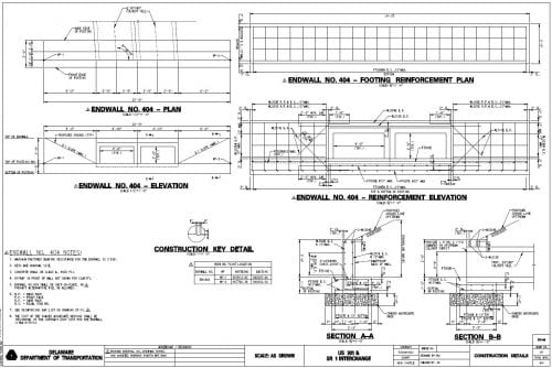
Figure 1Construction Plan Headwall Detail
We started exploring plan reading last Oct with a look at stationing and so in Jan nosotros explained various "views" one encounters in construction plans. If you idea those were exciting, you are going to dearest it as nosotros turn our attention to shop drawings and their nearly twin-brother, working drawings.
Let's think most the progression of plans from their earliest formulation. Somewhere at the starting time, a designer is sketching something out on a napkin or the dorsum of an envelope and that evolves into the design work, calculations, and and so forth. When the design is complete, a prepare of construction plans (and all the specifications and other supporting documents) come together to build the base of what will be the contract documents. But for many elements, the construction plans are not equally complete as they first appear. For whatever number of things, which we will explore here, the structure plans and specifications leave information technology upward to the contractor and subcontractors to detail how they intend to fulfill the contract requirements, the sources and materials they will use, temporary works, structural minutiae, and so on. This is where submittals, shop drawings and working drawings come in.

Figure 2 Itemize Cutting
The contractor will normally provide many submittals, depending upon the nature of the piece of work, including such things as projection schedules, sources of materials (aggregate, cement, etc.), design mixes (think physical or asphalt), hot/cold weather placement plans (think concrete), quality control plans, placement plans (eastward.1000., deck pours, heavy beam placement, etc.), repair details, catalog cuts for miscellaneous materials, etc. Store drawings and work drawings are normally idea of as categories of submittals.
Depending upon the agency procuring the work, shop drawings and working drawings are oft used interchangeably. In the Delaware Section of Transportation's (DelDOT) "Standard Specifications for Road and Bridge Construction," store drawings are defined every bit "contractor drawings that provide details for fabricating or constructing an chemical element of piece of work to be permanently incorporated into the projection," and working drawings are defined equally "drawings and information not in the contract that the contractor is required to submit to the engineer showing how the contractor will perform specific piece of work such as building cofferdams or falsework." While they are divers separately, only working drawings are included in the "consummate torso of documents" defining "contract," and they are largely lumped together with shop drawings throughout the Standard Specifications.

Figure 3 Construction Programme Reinforcing Bar Details
For our purposes, we won't dwell further on the distinction in terms and yous should instead pay close attention to how the specifications for your project defines them. Instead, permit'due south hash out the nature of some example shop drawings and how they chronicle to the construction or bid plans.
In general, shop drawings and working drawings prove in particular the proposed fabrication and assembly of structural elements, and the installation (i.due east., fit, and attachment details) of materials or equipment. They can include drawings, diagrams, layouts, schematics, descriptive literature, illustrations, schedules, performance and test data, and similar materials furnished by the contractor to explicate in particular specific portions of the piece of work required by the contract.

Effigy 4 Construction Plan Reinforcing Bar Details – Headwall Excerpt
In terms of what some retrieve of as working drawings, many projects have temporary support piece of work, false work, and the similar. For case, at that place may exist platforms to support bridge painting, containment systems, temporary steel plates, trench boxes, or a cofferdam to allow construction of footings in dry out atmospheric condition. While these may not be components of the terminal construction, they must be engineered to ensure they provide rubber to the workers and traveling public while also assuasive adequate room and support for the work to be completed properly. Normally, calculations and plans for these temporary works must be sealed by the Professional person Engineer completing the design. The contractor makes a submittal for acceptance past the owner agency (rarely does the owner's engineer "approve" the submittal – the design responsibility remains with the contractor).
A classic example of a shop cartoon would be for a drainage structure, such equally a storm drain inlet or a manhole. In the contract or bid documents, the construction will be sized and other details will be provided to guide the contractor's detailer as to the design requirements. The detailer in this example might be the precast visitor that will provide the structures. The detailer provides a much more complete set of drawings that bear witness thicknesses of walls, floors, and covers, reinforcing bar (rebar) details, joints, footstep placements, openings, reinforcing around openings, grates, lifting lugs, then on. In addition, in that location are usually catalog cuts for seals, sealants, grouts, mechanical pieces (like lifting lugs, steps, and grates), etc. By reviewing the shop drawing, the design engineer tin can be satisfied that what the precaster intends to build will be consistent with the blueprint intent and needs. Again, by and large, these also will require a Professional Engineer's seal from the detailer.
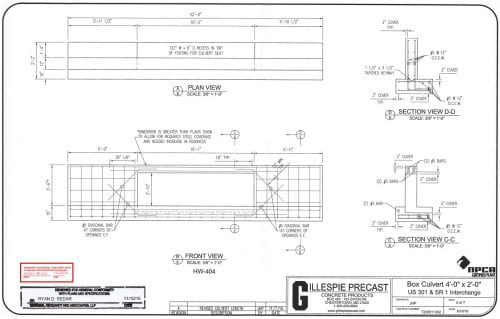
Figure v Headwall Shop Drawing
For precast or bandage-in-identify concrete structures of any kind, shop drawings are particularly of import for rebar details. These will show types and size of rebar (normally in lists), bending diagrams, location of each type of bar, lengths, tying schedules, splices, bar coatings, bar supports, aircraft and storage requirements, and other details.
Steel structures such every bit beams, bearings, shear connectors, or platforms require shop drawings as well. These volition include the type of steel to exist used in each chemical element, fastening (bolts, welds, gusset plates, rivets, etc.), dimensional details of the members, camber details, horizontal curve diagrams, general shop notes, splicing diagrams, stiffeners, and lots of lists. Here, the AASHTO/NSBA Steel Bridges Collaboration G1.three Store Detail Drawing Presentation Guidelines will ofttimes be the reference standard. In DelDOT'south Standard Specifications, a Professional person Engineer'due south stamp is not required for steel structure shop drawings.
Guardrail and stop treatment systems are all the same another typical example where shop drawings are required. For guardrail systems to perform as designed, no detail is too small – a missing washer or a substituted bolt can exist an unacceptable difference. As such, guardrail shop drawings will include items such equally the type of steel, coatings, and shape of the rail, but likewise the precise bolt patterns, the bolts, washers, and basics themselves, post designs and connections, as well as connections to structural members (such as span parapets) or finish treatments. Impact attenuators (known too past some xv other names) are terribly critical to safety performance, and then the attenuators themselves along with the connection details to the residuum of the guardrail system volition exist heavily detailed, as well as details for installation, such as bolt torque.
Street lighting (luminaires) are another example of installation that would normally crave shop drawings. These might accept the form of catalog cuts for simpler designs, but they notwithstanding must detail things similar the lamp types, materials, dimensions, crashworthy (if within the Clear Zone) connections, wiring connections, and so on. Of course, they must also demonstrate compliance with the design intent for light distribution and intensity (often past way of a mathematical model and plan), glare mitigation, light colors, etc.
These examples should give you an idea of the kind of shop drawings and working drawings that should play a part in your project and the role they play in the constructed project. In essence, these submittals (bated from the mixing and matching of names) fall into two basic categories. The first bargain with temporary or back up works, while the second can be thought of as detailing class, fit, and attachment details consistent with the design shown in the contract or bid drawings.
In most cases these days, the contractor submits shop drawings and working drawings and the owner'south engineer reviews the design documents for contract "conformance." The engineer then either returns them for revision or accepts them (sometimes with comments or requirements). Rarely does the owner'due south engineer "corroborate" the submittal these days, as the terminal responsibility for these details rests with the contractor.
Contractor submittals, including but not express to shop drawings and working drawings, are an essential office of contract management to ensure that, before elements are manufactured or installed, the work volition adjust with the blueprint intent and deliver the performance that is sought.
The Delaware T2/LTAP Center'south Municipal Engineering Circuit Rider is intended to provide technical assist and grooming to local agencies and so if you take construction management questions or other transportation issues, contact Matt Carter at matheu@udel.edu or (302) 831-7236.
Link to PDF
Source: https://sites.udel.edu/dct/2021/08/03/construction-plan-reading-basics-shop-drawings/
0 Response to "Shop Drawings Cut Lists Mechanical Plan"
Post a Comment